
Gantry Girder Design Case for 10t Box Type Gantry Crane – Part One
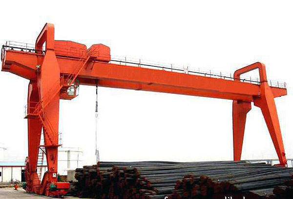
Gantry girder design and size for single girder gantry crane
Overall structure design of gantry crane bridge
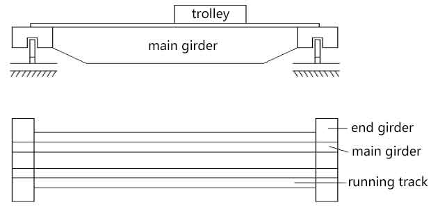
Box girder bridge structure of gantry crane is mainly composed of two main girders and two end girders.
Main gantry girder design: Main girder is the main force-summing element of gantry crane, which is composed with two webs on left and right, two cover plates on the upper and lower sides, large baffle, small baffle, and stiffened plate.
Upper camber design of main gantry girder: When loaded, the deflection deformation can be counteracted, which is produced under the condition of stiffness of main gantry girder, in order to avoid the load trolley climbing.
Main gantry girder deformation: When manufacturing the bridge of gantry crane, there is drawing residual stress after side welding. When the residual stress is released during the transportation and use, the two main gantry girders will be bent inwards. What’s more, under the action of horizontal inertia load, the main gantry girder is designed that allow to have a certain lateral bending under the condition of stiffness, superposition will cause large bending deformation.Trolley
Web wave deformation: Compression zone is less than 0.7δ0, tensile zone is less than 0.2δ0. It is beneficial to improve the stability and service life of the crane by the lower wave deformation.
Levelness of upper cover is less than or equal to b/250, verticality of the web is less than or equal to h0/200, b is the width of cover plate, h0 is the height of gantry girder. End girder is one of the main parts of gantry crane bridge, which is usually adopts box structure, and rigid connection with main gantry girder in the horizontal plane. It can be divided into the following two types according to the loaded condition:
- End girder bears the maximum supporting press of the main gantry girder, which is meaning that there is vertical load acts on the end girder.
- There is no vertical load on the end girder, it only plays the role to connect with main girder of gantry crane.
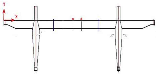
Geometrical size design of main gantry girder
Section selection and checking of gantry girder
It is usually according to the condition of stiffness and strength, and minimize the sectional area, meet the construction requirements (such as the maximum height of gantry crane girder and platform welded girder is limited) to guarantee the height of gantry crane girder, then preliminarily estimate the thickness of web and cover plate, calculate the geometric characteristics of cross section, and then check, adjusted properly until qualified.
Main Gantry Girder Design
| Lifting Capacity | Span | Model | Lifitng Height | Lifting Speed | Running Speed of Trolley | Running Speed of Bridge |
|---|---|---|---|---|---|---|
| 10t | 30m | Mh-10-30 | 16m | 3.5m/min | 20m/min | 24.4m/min |
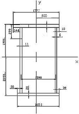
Section Size Design of Main Gantry Girder
Span: L=30m
Central height: h =1/20L=1.5m
Height of end girder connection parts: h1=0.5h=0.75m
Trapezoid height: c=1/10L=3m
Width of end girder: 2C0=0.5H1=0.5×0.7m=0.375
Web wall spacing: b0=700mm
Thickness of web:δ0=6mm
Width of cover plate: b= b0+2(δ0+20)mm=700=2×(6+20)mm=752mm≈750mm
Large partition spacing: near the end girder a=h0=1970mm
Span centre a=1.5h0=1.5×1.37m=2.055m
Small partition height: h2=h0/3=456m≈450mm
Small partition spacing: a1=0.5h0=684mm≈680mm
The longitudinal stiffener angle: h3=0.25h0=342mm≈340mm
Force analysis of main gantry girder
Load calculation: q=80N/cm
Concentrated fixed load: Operating mechanism weight G1, spacing L1
Cabin weight G2, spacing L2
Electrical equipment G3, spacing L3
Select motor
Static power of motor: P=3.3KW
Select reducer
Wheel speed: nc=Vdc/(π×Dc)
Mechanism transmission ratio: i=n1/nc=705/57.3=12.3
Travelling load: F=77.5t
Wheel pressure of each wheel: F1=F2=F/4=190KN
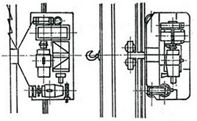
Diagram of Single Girder Trolley
Dead weight of trolley: Gx=172KN
Horizontal distributed load: qsh=1/10q=8N/cm
Horizontal concentrated load: Fsh=(F1+F2)/10=38KN
Irregularity of crane track will cause the vibration of bridge and main girder, thus distributed load and concentrated load will produce dynamic loading, which should also be estimated in fixed load. The dynamic loading can be considered by an impact factor K, K is 1.1.
G0’=1.1G0=14KN
G2’=1.1×2×9.8=21.56KN
q’=1.1q=88N/cm
In the next article, we will continue to talk about the gantry girder design, which will mainly focus on the checking for various of parameters of gantry girder.

The gantry crane is a bridge type crane with the shape of a portal frame set on two legs. There are many types of gantry crane. Today we will share some common used....
Gantry crane is a kind of overhead crane, you may have many confusions when choose your gantry crane. Today, I will give you some suggestion to help you choose a suitable gantry crane....
EOT crane safety is important for crane operators, we summed up 21 necessary operation safety tips for EOT crane, hope the EOT crane operator can obey strictly....